NOTE: At this time, bitmaps are only supported in CADFusion projects that target the A3200 motion control system.
Bitmaps and bitmap tools configure the A3200 PSO to mark a bitmap image by using a tool that is attached to your system, such as a laser. Marking information is read from a .bit file and is downloaded to the drive. The PSO hardware can then use the marking information. PSO ARM and PSO OFF commands execute at specified times with coordinated motion commands to scan the bitmap and mark the pixels by turning on or pulsing the PSO output.
A tool has four phases. The table that follows shows the code that is generated for each phase of a Bitmap tool and the specified time in a program when the code executes.
Table: Tool Phases and Code Execution
| Tool Phase | Bitmap Code | Description |
|---|---|---|
|
Initialization |
Not available |
Bitmap tools do not have code that executes during the Initialization phase. |
|
On |
Open .bit file PSO Initialization Code |
Before the bitmap starts, the applicable .bit file opens and the PSO hardware initializes. |
|
Off |
Close .bit file |
After the bitmap completes, the .bit file closes. |
|
Teardown |
Not available |
Bitmap tools do not have code that executes during the Teardown phase. |
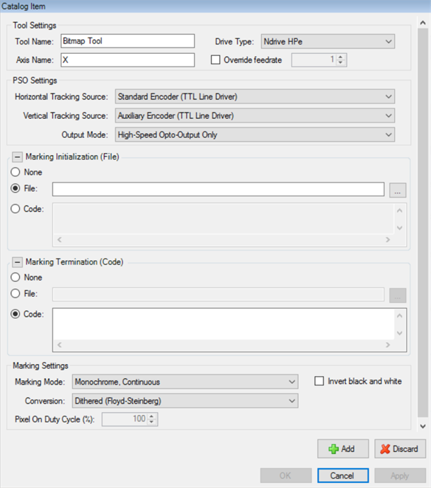
Use the Tool Catalog tab of the Catalog Manager to add or edit tools. For more information, refer to Add Tools or Edit Tools.
| Tool Setting | Description |
|---|---|
|
The name of the tool. Each tool in your project must have a unique name. |
|
|
The name of the axis on which PSO is commanded to mark the bitmap. |
|
|
The type of drive on which PSO is commanded to mark the bitmap. |
|
|
Select the box if you want to specify the feedrate used to mark the bitmap that uses this tool. If you do not specify the feedrate, CADFusion uses the Bitmap Marking Feedrate from the project settings. |
|
|
The tracking sources that are applicable to the horizontal and vertical axes that are used to mark the bitmap. The axes show on the canvas. For some Drive Types, you must configure more properties. |
|
|
Marking Initialization |
Configure the AeroBasic code that executes before the first marking scan. If it is necessary for marking to pause to download more data to the drive, the Marking Initialization code also executes before the marking scan that occurs immediately after the pause.
For more information, refer to How Bitmaps Are Marked. |
|
Marking Termination |
Configure the AeroBasic code that executes after the last marking scan. If it is necessary for marking to pause to download more data to the drive, the Marking Termination code also executes after the marking scan that occurs immediately before the pause.
For more information, refer to How Bitmaps Are Marked. |
|
Marking Settings |
The marking settings specify the effect of each pixel on the output connected to the tool that you use to mark the bitmap. You can specify these Marking Modes. Each Marking Mode has different marking settings that you can specify. Specifies how you want grayscale values to be converted to black or white values. You can select Floyd-Steinberg dithering, or you can use a threshold that is calculated from the image that you specify. Typically, darker areas of the bitmap cause the output to turn on. And, the lighter areas cause the output to turn off. Select the box if you want the lighter areas of the bitmap to cause the output to turn on and the darker areas to cause the output to turn off. Conversion Specifies how you want grayscale values to be converted to black or white values. You can select Floyd-Steinberg dithering, or you can use a threshold that is calculated from the image that you specify. Specify the width of the pulse that is generated at each black pixel as a percentage of the total width of each marking pixel. Invert black and white Typically, darker areas of the bitmap cause the output to turn on. And, the lighter areas cause the output to turn off. Select the box if you want the lighter areas of the bitmap to cause the output to turn on and the darker areas to cause the output to turn off. Specify a collection of grayscale values and their related pulse widths as a percentage of the total width of each marking pixel. CADFusion uses linear interpolation and the values that you specify to calculate the pulse widths for all possible grayscale values, 0 through 255. Invert black and white Typically, darker areas of the bitmap cause the output to turn on. And, the lighter areas cause the output to turn off. Select the box if you want the lighter areas of the bitmap to cause the output to turn on and the darker areas to cause the output to turn off. For more information, refer to How Bitmaps Are Marked. |